Form Energy · Root cause analysis
Hydrogen event — 8D investigation
A loud bang on first charge of the first field prototype — and the eight weeks that followed.
The chemistry
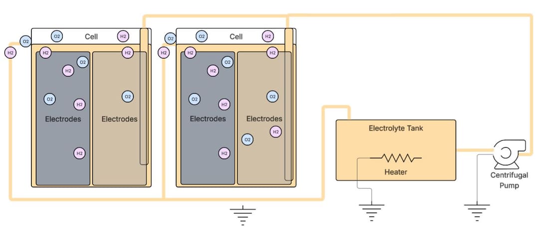
The cell runs on reversible rusting. Discharging supplies oxygen from air and converts iron to rust, releasing electrons; charging drives it back. During charge the desired anode reaction is Fe(OH)₂ + 2e⁻ → Fe + 2OH⁻ — but water is present in enormous quantity, and if the potential goes far enough negative, water is reduced instead: 2H₂O + 2e⁻ → H₂ + 2OH⁻. As charge proceeds, side reactions increasingly compete, and the cell produces hydrogen.
The event
During the first charge of the 40-foot enclosure — the first field prototype — the team heard a loud bang and operations stopped completely. I was placed as team lead to find the root cause and propose short and long-term solutions.
How we ran it
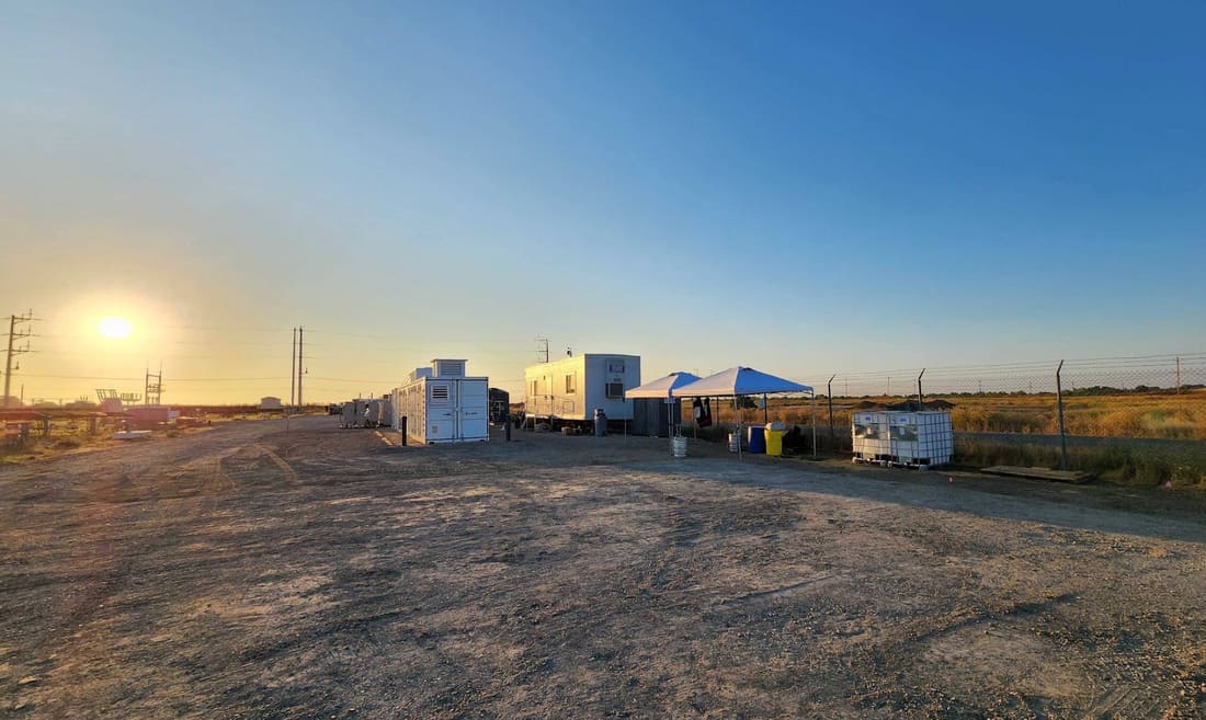
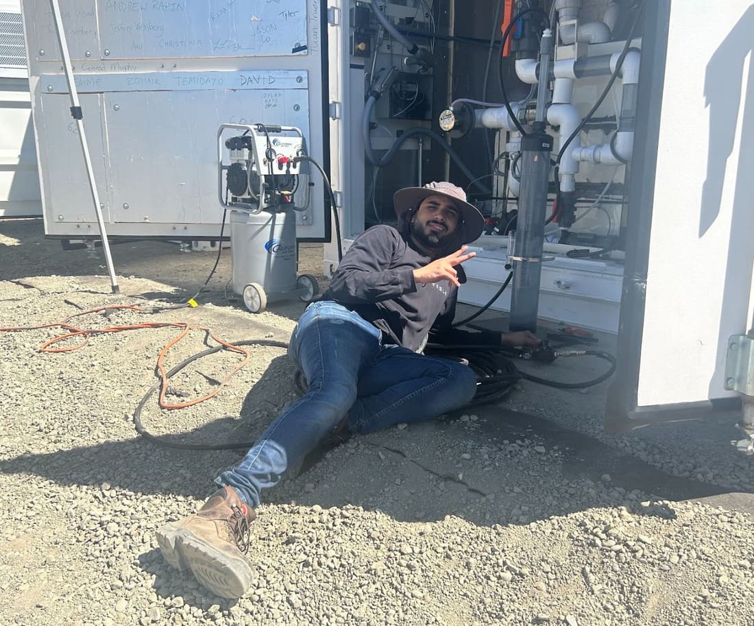
Eight weeks on site: four to identify every root cause, two to test short-term fixes in the lab, two to integrate them in the field. A field team of three — myself, an EE and a technician — worked six modules at 30 cells each, with a parallel lab team testing hypotheses under controlled conditions. Bi-weekly executive review, daily engineering sync, and fishbone plus 8D as the framework, chosen specifically to avoid analysis paralysis.
What the data said
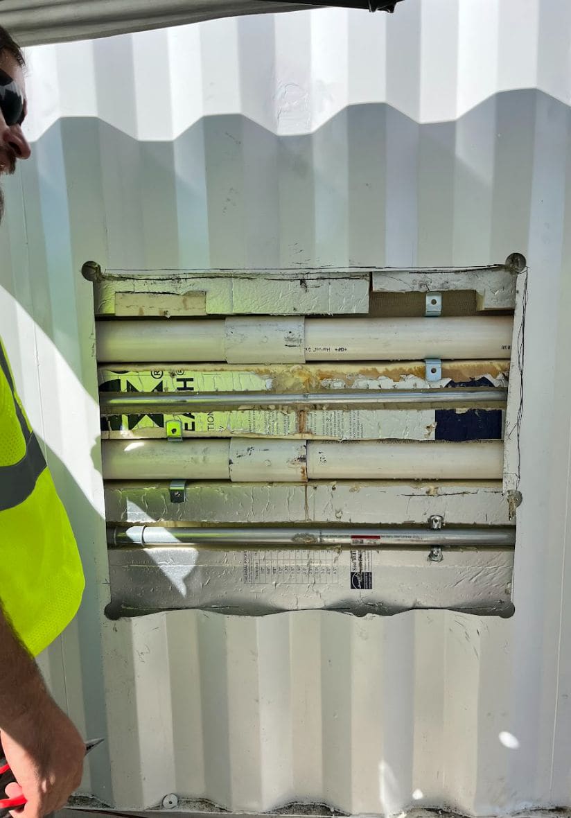
Isolation loss appeared the moment charge was initiated. Cells had arrived 70% charged so string voltage was already high — the first test ever at that voltage. The isolation interlock had been disabled on the assumption it was a false trip, since isolation was steady during discharge and every cell and module had been tested before deployment. Visual inspection found electrolyte leaking from plumbing and joints.
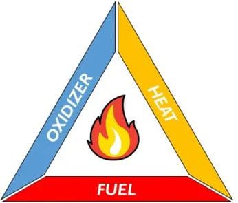
Root cause — a complete fire triangle
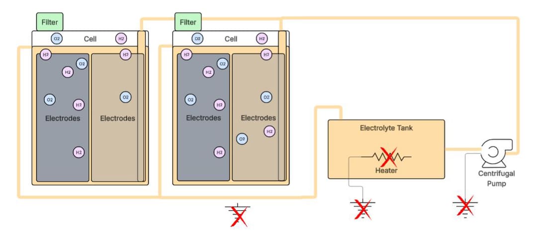
Electrolyte swell during charge caused leaks through interfaces and contact via the overflow port, and the pump, heater and metal brackets all provided a ground path to that leaking electrolyte — the ignition source, and exactly the isolation loss seen at charge initiation. Hydrogen evolution built up in the cell headspace to within its explosive limits of 4% to 75% — the fuel. Oxygen is present in that same headspace during charge as a product of the reaction — the oxidiser. All three legs at once.
Solutions
Short term: reduce electrolyte level to remove the overflow arc path, with thermal characterisation at the lower level; remove every electrical ground path via plumbing, pumps and heater; update the SOP so those components are never live during charge. Long term: enhance seals against electrolyte creep through HV joints, add a permeable membrane that vents hydrogen while trapping electrolyte, isolate the pump on brackets, and remove the heater entirely.
Why the heater had to go
Each cell holds 50 L of electrolyte at 4.184 kJ/kg·K. A 40 K rise needs 8,360 kJ — about 2.3 kWh per cell. With 300 cells in an enclosure served by a single 5 kW heater, reaching optimal operating temperature would take roughly six days, and the auxiliary load would erode round-trip efficiency further. The heater was not a marginal component to protect; it was a ground path buying nothing.
Outcome
The investigation drove an architectural change in how the company approached electrolyte and hydrogen mixing under both charge and discharge — not a containment fix bolted onto the existing design, but a change to the thing generating the risk.