Tesla · Thermal design
Planar magnetics integration
Integrating magnetics into the PCB removes cost but moves a lot of heat into a structure that was never a heatsink.
What was integrated
Two low-frequency chokes, two DC-AC transformers and two DC-DC transformers, all absorbed into the PCB structure with no wire-wound magnetics remaining.
The thermal problem
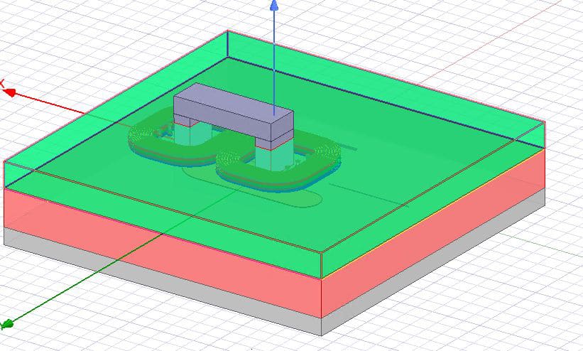
Modelled in ANSYS Icepak with power losses imported from the electrical team’s Maxwell simulation, against a 70 °C internal ambient, 32 Arms primary winding and 65 °C coolant. Without a conduction path the design is not survivable: 300 °C peak on natural convection alone.
| Thermal stack | Peak temp | Outcome |
|---|---|---|
| No TIM, natural convection | 300 °C | Not viable |
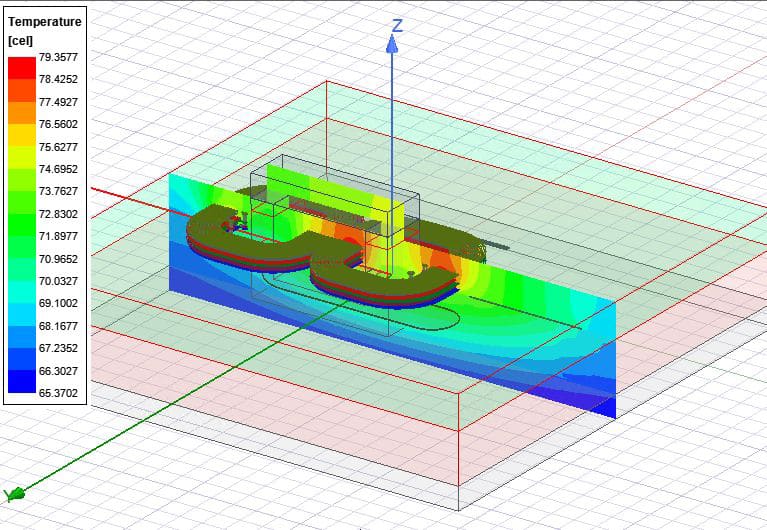
| TIM full contact to heatsink (4.4 mm, k = 3.6 W/mK) | 80 °C | Design point |
| 1.5 mm busbar on the primary | 97 °C | Workable, worse than TIM |
The conduction path decides it
Adding thermal interface material in full contact from the PCB underside to the heatsink — 4.4 mm height, k = 3.6 W/mK, 1 mm thick — brings the peak to 80 °C. A 1.5 mm busbar on the primary instead reaches 97 °C: workable, but worse than the TIM path.
Validation
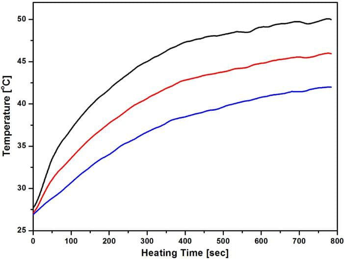
Simulation was validated against thermocouples on coupon-level samples. Where model and bench disagreed, the corrected self-heating and power losses went back into the model — so the next design was constrained by something already proven wrong once.