HEN Technologies · Flow sensing
Stream IQ
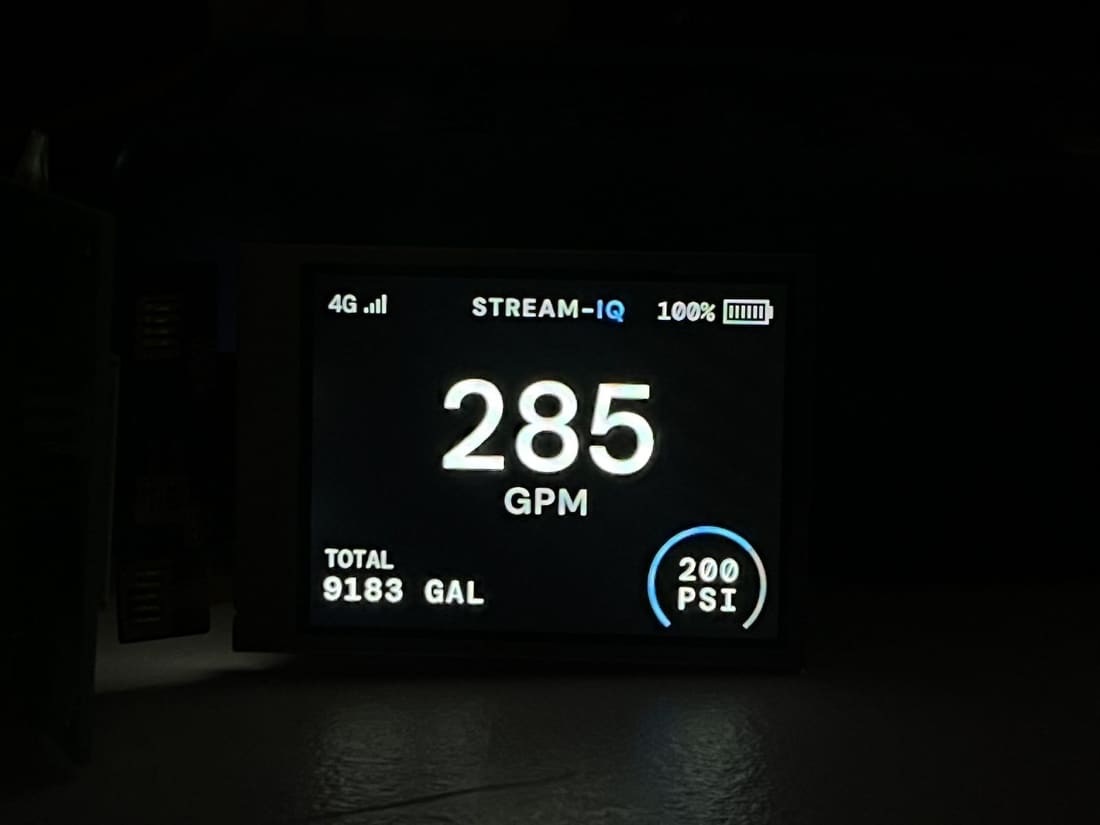
An intelligent flow meter that tells crews what their line is actually doing — real-time flow and pressure, with no moving parts in the waterpath.
The problem
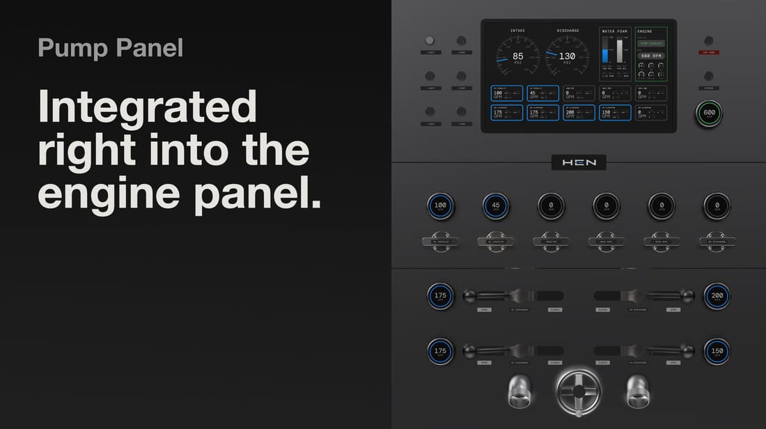
Fire crews cannot directly verify nozzle flow. It gets inferred from pump pressure and radio calls, so the number everyone acts on is an estimate — and friction loss, kinks and restrictions all move it without anyone knowing.
Sensing approach
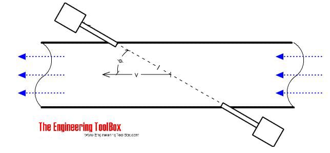
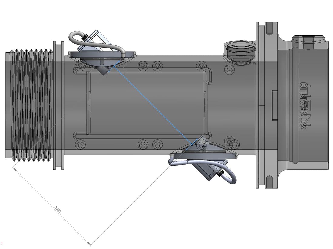
Transit-time ultrasonic measurement: a pulse travels with the flow, then against it, and the difference in arrival time gives velocity. At 1 MHz through a 2.5" waterway with transducers 76 mm apart at 46° to the flow, the timing differences are tiny — which is why resolution, not raw signal, sets the accuracy floor.
Bubble entrapment
DOE testing showed how sensitive the ultrasonic path is to air trapped at the sensor face. The mechanical design exists largely to guarantee the sensor head stays immersed regardless of orientation or flow state.
Why accuracy is worse at low flow
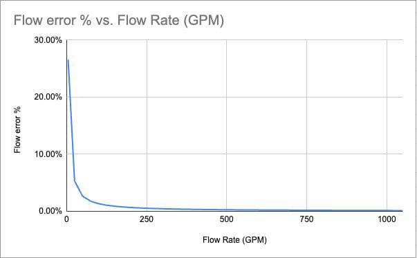
Flow is derived from a timing signal against a fixed measurement resolution. When the time difference is small, a single nanosecond of error is a large fraction of the reading; when it is large, the same nanosecond barely matters. Ultrasonic sensing is therefore inherently more accurate at high flow — like measuring short distances with a coarse ruler.
Calibration
Initially calibrated against a known turbine flow sensor, but an ultrasonic design needed its own methodology to expose its real limits. Final calibration ran against five machined smooth-bore nozzles across ten flow-versus-pressure profiles, with temperature compensation added because water density moves with temperature, and software filtering to hold the data within spec.

Field validation
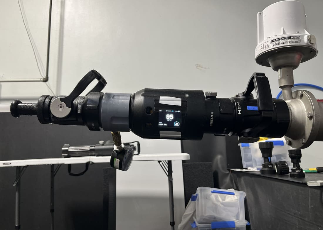
Tested in the lab and in the field with pump operators and fire departments, specifically to understand how bubbles and debris behave in real hose lines rather than clean bench conditions.
The device
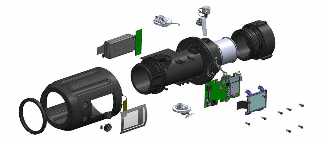
A full-bore waterpath with no moving parts and minimal pressure loss, in a sealed IP67 housing: main board and display, battery, sensing elements on the waterway body, and 2.5" NH couplings at both ends. Everything that has to survive the fireground sits inside one impact-resistant shell.
What I led
Hardware roadmap and end-to-end architecture. Hired and led the mechanical, electrical and firmware engineers. Sensing design, sealing and enclosure, reliability, field calibration capability, and the data pipeline behind the Fluid IQ platform.